Home
|
Fishing Swivel Patents
PATENT ABSTRACTS OF JAPAN
- SWIVEL FOR FISHING LINE AND METHOD FOR PRODUCING THE SAME
- DEVICE FOR FISHING TACKLES
- TERMINAL TACKLE FOR FISHING
- SWIVEL-ATTACHING STRUCTURE
- FISHING SWIVEL
- SWIVEL FOR FISHING TACKLE
- UNTWISTING TOOL FOR FISHING LINE AND ROTATION PROMOTING MEANS FOR UNTWISTING TOOL FOR FISHING LINE
- CONNECTIVE IMPLEMENT FOR FISHING
- PRODUCTION OF TWIST-RETURNING MATERIAL FOR FISHING LINE AND PRODUCTION OF TWIST RETURNER FOR FISHING LINE
SWIVEL FOR FISHING LINE AND METHOD FOR PRODUCING THE SAME
| (11) Patent Publication number : |
2001-211792 |
| (43) Date of publication of patent application : |
07.08.2001 |
| (21) Patent Application number : |
2000-026941 |
(71) Patent Applicant : |
ONO KINZOKU KOGYOSHO:KK |
| (22) Date of filing : |
04.02.2000 |
(72) Patent Inventor : |
ONO SHINKO
MORI TOSHIO |
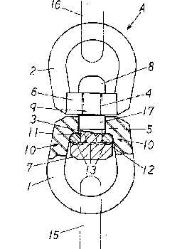 Abstract:
PROBLEM TO BE SOLVED: To provide a fishing line swivel that can
promptly and surely remove the line twisting applied to branched lines
during the fishing and provide a method that can produce the swivels
for fishing of light weight and compact size.
SOLUTION:
A plurality of balls 13 are fitted to the rotary seat 11 provided on
the boss 5 in the first torus 1, the second head 8 of the linking shaft
9 is inserted and the pushing seat 12 of the first head 7 in the liking
shaft 9 is allowed to come into contact with the balls. In addition,
the second heat 8 of the linking shaft 9 is inserted into the linking
hole 4 of the boss 56 in the second torus 2 and the boss 6 of the
second torus 2 is squeezed and the second head 8 is connected to the
boss 6 in the second torus 2.
|
DEVICE FOR FISHING TACKLES
| (11) Patent Publication number : |
2000-139302 |
| (43) Date of publication of patent application : |
23.05.2000 |
| (21) Patent Application number : |
10-314511 |
(71) Patent Applicant : |
KUSUMOTO HARUYUKI |
| (22) Date of filing : |
05.11.1998 |
(72) Patent Inventor : |
KUSUMOTO HARUYUKI |
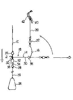 Abstract:
PROBLEM TO BE SOLVED: To provide fishing tackles capable of preventing
a hook from twining around themselves or the like and capable of
imparting good catch of fish to us.
SOLUTION: The fishing tackles comprise (A) a T-shape metal fittings 16 consisting of a basic pillar 12 linked with a fishing
main line 10, (B) a branched pillar 14 rotatable in a nearly T-shaped
state to the pillar 12 and linked with the pillar 12 in a vertically
turnable state, (C) a flexible bar rope 18 linked with the end of the
pillar 14 and (D) a swivel 22 linked with the end of the rope 18 and for tying a leader 20.
|
TERMINAL TACKLE FOR FISHING
| (11) Patent Publication number : |
11-151058 |
| (43) Date of publication of patent application : |
08.06.1999 |
| (51) Int.CI.
A01K 91/06 A01K 91/00
|
| (21) Patent Application number : |
09-318499 |
(71) Patent Applicant : |
YOSHIMURA ICHIRO |
| (22) Date of filing : |
19.11.1997 |
(72) Patent Inventor : |
YOSHIMURA ICHIRO |
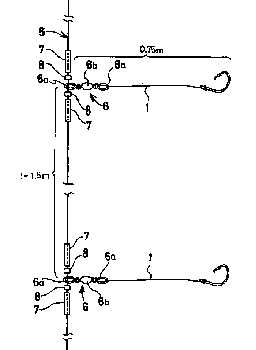 Abstract:
PROBLEM TO BE SOLVED: To provide a lightweight terminal tackle for fishing
capable of readily attaching branch lines at a prescribed interval to a
long main line without cutting the main line to a length corresponding
to the attaching interval of the branch lines and without making a swivel conspicuous.
SOLUTION: This terminal tackle for fishing is obtained by annularly
attaching a swivel 6 prepared by binding each branch line 1 to a main
line 5 comprising plural series of fishing
lines composed of a length exceeding the attaching interval of the
branch lines l and securing a pair of twist runback positioning
elements 7 to the main line 5 so as to sandwich the swivel 6.
|
SWIVEL-ATTACHING STRUCTURE
| (11) Patent Publication number : |
09-271306 |
| (43) Date of publication of patent application : |
21.10.1997 |
| (51) Int.CI.
A01K 91/047 A01K 91/18
|
| (21) Patent Application number : |
08-110295 |
(71) Patent Applicant : |
YAHIRO YOSHITAKE |
| (22) Date of filing : |
06.04.1996 |
(72) Patent Inventor : |
YAHIRO YOSHITAKE |
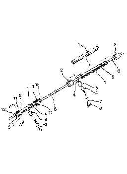 Abstract:
PROBLEM TO BE SOLVED: To obtain a swivel-attaching structure producible
at a low cost and effective for preventing the lowering of the strength
of a fishing line to prevent the breakage of the line and improve the
durability of the line, enabling easy and sure attachment of a swivel
by anyone without necessitating skill in press- fixing work and
improving the workability of swivel-attaching work.
SOLUTION: A flexible tube 1 is put on a fishing
line snood 6, metallic press- fixing tools 2 are put on both ends of
the tube 1 protruding from the tools, the press-fixing tools are
plastically deformed by pressing to fix the snood 6, the tube 1 and the
press-fixing tool 6 and a ring 4 of a swivel 3 is put on the outer circumference of the tube 1 between the press-fixing tools 2.
|
FISHING SWIVEL
| (11) Patent Publication number : |
09-172921 |
| (43) Date of publication of patent application : |
08.07.1997 |
| (21) Patent Application number : |
07-335139 |
(71) Patent Applicant : |
TSURIKEN:KK |
| (22) Date of filing : |
22.12.1995 |
(72) Patent Inventor : |
TANAKA EIICHI |
 Abstract:
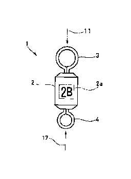
PROBLEM TO BE SOLVED: To provide a fishing swivel capable of simply and accurately securing a floating state.
SOLUTION: This fishing swivel
1 for connecting a main line 11 to a leader 17 is equipped with a
weight indication part 2a having marked an empty weight at a proper
part on the surface of a main body 2 of the swivel. The empty weight of
the weight indication part 2a is set by the same marking method as that
of a lead ball in a fishing terminal tackle. Both the ends of the main
body 2 of the swivel
are provided with retaining rings 3 and 4 for binding the main line 11
and the leader 17, respectively. The retaining ring 3 at the main line
11 side is formed larger than the retaining ring 4 at the leader 17
side. Preferably, the retaining rings 3 and 4 are subjected to powder
coating.
|
SWIVEL FOR FISHING TACKLE
| (11) Patent Publication number : |
07-039287 |
| (43) Date of publication of patent application : |
10.02.1995 |
| (21) Patent Application number : |
05-211010 |
(71) Patent Applicant : |
MIYOSHI SEISAKUSHO:KK |
| (22) Date of filing : |
03.08.1993 |
(72) Patent Inventor : |
INABA NOBUAKI |
 Abstract:
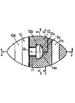
PURPOSE: To provide a lightweight swivel for fishing tackles, commonly
named corkscrew swivel or swivel having a sufficient strength without
causing the galvanic corrosion or rusting.
CONSTITUTION: This swivel for fishing
tackles is constructed from a male member 10, made of a synthetic resin
and having a protruding part (10b) and a female member composed of two
members 11 and 12, mutually adhered thereto on a surface 13 along the
center line of a recessed part rotatably engaging with the protruding
part (10b) and respectively provided with semirecessed parts (11a) and
(11b) corresponding to 1/2 of the recessed part and made of a synthetic
resin.
|
UNTWISTING TOOL FOR FISHING LINE AND ROTATION PROMOTING MEANS FOR UNTWISTING TOOL FOR FISHING LINE
| (11) Patent Publication number : |
2002-345379 |
| (43) Date of publication of patent application : |
03.12.2002 |
| (51) Int.CI.
A01K 91/047 A01K 75/00
|
| (21) Patent Application number : |
2001-158175 |
(71) Patent Applicant : |
ONO KINZOKU KOGYOSHO:KK |
| (22) Date of filing : |
28.05.2001 |
(72) Patent Inventor : |
ONO SHINKO
MORI TOSHIO |
 Abstract:
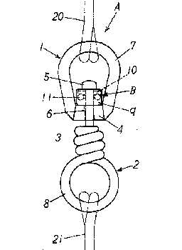
PROBLEM TO BE SOLVED: To provide both a light and compact untwisting
tool for a fishing line, with which a twist of a fishing line can be
rapidly and surely untwisted and a rotation promoting means for an
untwisting tool for a fishing line.
SOLUTION: This untwisting tool A for a fishing line
is equipped with the rotation promoting means B between the upper part
of a boss part 4 of a one- way rotor 1 and the lower part of a head
part 5 of a connection shaft 3. The rotation promoting means is
equipped with a first member 9 to be brought into contact with the
surface of the upper part of the boss part of the one-way rotor, a
second member 10 which corresponds to the first member and is to be
brought into contact with the surface of the lower part of the heat
part of the connection shaft, a plurality of rolling bodies 10 laid
between the first member and the second member and a first through hole
12 and a second through hole 13 which are bored at the central part
between the first member and the second member and into which the
connection shaft is inserted are arranged.
|
CONNECTIVE IMPLEMENT FOR FISHING
| (11) Patent Publication number : |
11-000088 |
| (43) Date of publication of patent application : |
06.01.1999 |
| (21) Patent Application number : |
09-168001 |
(71) Patent Applicant : |
MARUKIN:KK |
| (22) Date of filing : |
09.06.1997 |
(72) Patent Inventor : |
KANEKO KOJI |
 Abstract:
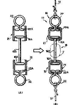
PROBLEM TO BE SOLVED: To provide the subject implement not damaging a
fishing line and snell, capable of attaching a sinker with its attached
point in order, also simple to attach the sinker.
SOLUTION: This implement has such a scheme that a fishing line
12 is fastened to the ring 22 of a 1st connective part 14, while a
snell 13 to that of a 2nd connective part 15; a sinker 17 is nippedly
set on a metallic wire 16; as a result, the fishing line becomes hard to entangle, preventing itself from twisting;
a sinker positioning is facilitated; a bait can also be sunk naturally
because the sinker 17 can be set in close proximity to the snell 13;
further, use of the metallic wire for sinker attachment damages no fishing line and snell due to the sinker.
|
PRODUCTION OF TWIST-RETURNING MATERIAL FOR FISHING LINE AND PRODUCTION OF TWIST RETURNER FOR FISHING LINE
| (11) Patent Publication number : |
04-131031 |
| (43) Date of publication of patent application : |
01.05.1992 |
| (51) Int.CI.
A01K 91/047 B22F 3/02 B22F 3/10 B29C 45/00
|
| (21) Patent Application number : |
02-253526 |
(71) Patent Applicant : |
ONO KINZOKU KOGYOSHO:KK |
| (22) Date of filing : |
21.09.1990 |
(72) Patent Inventor : |
ONO SHINKO |
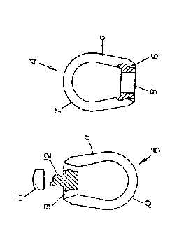 Abstract:
PURPOSE: To produce the subject twist-returning
material having uniform component in high yield a large amount within a
short time under saving labor by mixing a base material comprising
metallic powder and a viscous joining material, subjecting to injection
molding, pressing in a mold and calcining.
CONSTITUTION: Metallic
powder such as stainless steel or nickel preferably having 0.1-10μm
granular diameter is mixed with an oil and fat-based viscous liquid
joining material, and a first revolving ring 4 having a boss part 6 and
a ring part 7 and a second revolving 5 having a base part 9 and a ring
part 10 are molded by an injection molding machine. Resultant rings are
respectively presses in molds and calcined preferably at 800-1200°C,
then a joint shaft 12 of the second revolving ring 5 is inserted into
an open hole 8 of the first revolving ring 4 and the two rings are
joined by nipping the open hole with a nipping tool to afford the
objecting twist-returning material.
|
|
 Abstract:
 Abstract:
 Abstract:
 Abstract:
 Abstract:
 Abstract:
 Abstract:
 Abstract:
 Abstract: