The following patents relating to chemical sharpening techniques do
not specifically refer to fishing hooks but I presume the technology
has some relevance to fishing hook sparpening. I will continue to try
to find patents specifically relating to the chemical sharpening
of fishing hooks.
Here are some general comments about chemical sharpening of fishing hooks that I have found on other wesbites -
A method is described for forming sharp tips on thin wires, in particular
phosphor bronze wires of diameters such as one-thousandth inch used to
contact micron size Schottky barrier diodes, which enables close control
of tip shape and which avoids the use of highly toxic solutions. The
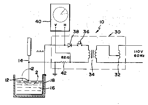
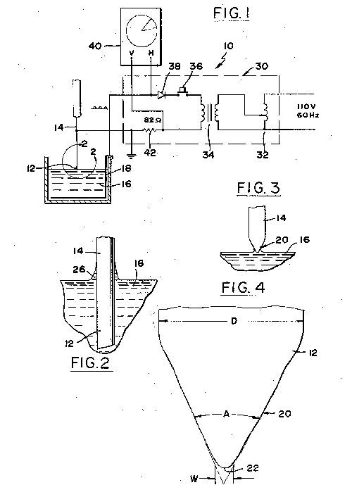
method includes dipping and end (12) of a phosphor bronze wire (14) into a
dilute solution (16) of sulfamic acid and applying a current through the
wire to electrochemically etch it. The humidity in the room is controlled
to a level of less than 50%, and the voltage applied between the wire (14)
and another electrode (18) in the solution is a half wave rectified
voltage. The current through the wire is monitored, and the process is
stopped when the current falls to a predetermined low level.
Images
Method and apparatus for resharpening cutting tools by electropolishing
process
| United States Patent |
4,406,759
|
|
Saitoh
|
September 27, 1983
|
Abstract
A method and apparatus for resharpening cutting tools having an edge of
complex curve by electropolishing process, wherein after a protective film
is formed on the non-polished surface of the edge of a cutting tool, the
edge is immersed in an electrolytic solution and DC voltage is applied
between the tool, which serves as an anode, and a cathode plate immersed
in the solution to thereby polish the edge by dissolving.
| Inventors:
|
Saitoh; Joichi (Hotarugaike-higashi, JP)
|
| Assignee:
|
Kotobuki Seihan Printing Co., Ltd. (Osaka, JP)
|
| Appl. No.:
|
313179 |
| Filed:
|
October 20, 1981 |
Foreign Application Priority Data
|
Nov 22, 1979[JP] |
54-151644 |
|
Jun 09, 1980[JP] |
55-77531 |
| Current U.S. Class: |
205/646; 205/664; 205/680 |
| Intern'l Class: |
C25F 003/00; C25F 003/14 |
| Field of Search: |
204/129.55,129.65,129.9,129.95,129.35,129.46
|
References Cited [Referenced By]
U.S. Patent Documents
| 3762243 |
Oct., 1973 |
Borrkfield |
204/129.
|
| 4217190 |
Aug., 1980 |
Neal et al. |
204/129.
|
| Foreign Patent Documents |
| 186822 |
Jan., 1967 |
SU |
204/129.
|
Primary Examiner: Kaplan; G. L.
Assistant Examiner: Nguyen; Nam X.
Attorney, Agent or Firm: Armstrong, Nikaido, Marmelstein & Kubovcik
Parent Case Text
This is a division of application Ser. No. 206,081, filed Nov. 12, 1981,
now U.S. Pat. No. 4,331,515.
Claims
What is claimed is:
1. A method of resharpening cutting tools by electro-polishing process,
comprising the steps of forming a protective film on a non-polished
surface of an edge of the tool, immersing said edge in an electrolytic
solution, applying a DC voltage between said tool serving as an anode and
a cathode, which is immersed in said electrolytic solution, for a
predetermined time to thereby polish said edge by dissolving and removing
said protective film.
2. A method as set forth in claim 1, wherein said protective film is formed
by mixing vinyl acetate, varnish, and a mixture of 60% by volume of
phthalic acid and 40% by volume of cellulose acetate, in equal amounts, to
prepare a solution, applying said solution to the tool and drying the
same.
3. A method as set forth in claim 1, wherein said electrolytic solution is
an aqueous solution of 90% by volume of phosphoric acid and 1% by volume
of sulfuric acid.
Description
BACKGROUND OF THE INVENTION
The present invention relates to a method and apparatus for resharpening
cutting tools made of metal, particularly tools having a cutting edge of
complex curve, such as those used for punching out printed matter, by
electropolishing process.
Conventionally, the resharpening of cutting tools has been performed
manually or mechanically by using grindstones or files. With such
conventional method, there may not be so much problem involved in
resharpening cutting tools having a simple cutting edge, but in the case
of tools used for punching out printed matter into complex shapes, the
cutting edge of complex curve of the tool has numbers of concaves and
convexes, making mechanical resharpening impossible and forcing the
operator to resort to manual resharpening, which takes much time and
labor.
Further, satisfactory resharpening requires a great deal of skill. Thus,
another disadvantage is that all operators cannot always resharpen the
tool satisfactorily.
SUMMARY OF THE INVENTION
With the above problems in mind, the present invention has been
accomplished.
Accordingly, a first object of the invention is to provide a method whereby
tools having a cutting edge, however complex, can be quickly and easily
resharpened without using any grindstone of file.
A second object of the invention is to provide a method capable of putting
a very sharp edge on a tool and ensuring that the required
after-processing is easy.
A third object of the invention is to provide an apparatus for resharpening
tools by electropolishing process, wherein tools can be readily and
quickly resharpened and the apparatus is easy to handle and particularly
facilitates immersion of tools in the electrolytic solution and removal of
them from the latter.
A fourth object of the invention is to provide an electropolishing
apparatus which is capable of easily resharpening tools having a cutting
edge, however complex, and which is easy to handle.
A fifth object of the invention is to provide an electropolishing apparatus
for resharpening cutting tools, wherein DC current for polishing can be
automatically controlled by a timer and deterioration of the polished edge
can be prevented and wherein a predetermined current value can be set
according to the size of a cutting tool to be polished.
These and other objects and features of the invention will become more
apparent from the following description of embodiments with reference to
the accompanying drawings.
BRIEF DESCRIPTION OF THE DRAWINGS
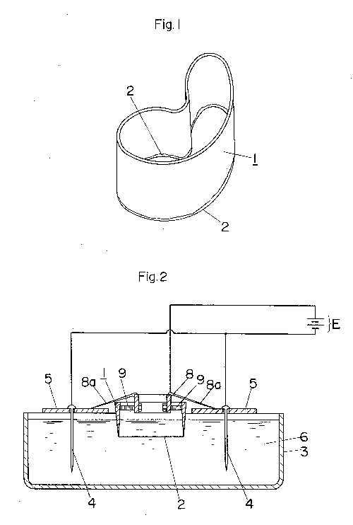
FIG. 1 is an enlarged perspective view of a cutting tool to be resharpened
by the present invention;
FIG. 2 is a sectional view of an electropolishing tank according to the
invention;
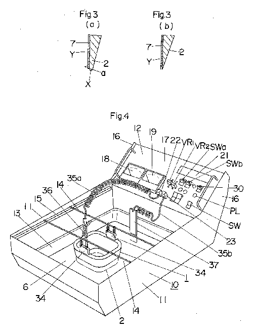
FIGS. 3a and 3b are enlarged fragmentary sectional views of a cutting tool
before and after the edge is resharpened, respectively, by the present
invention;
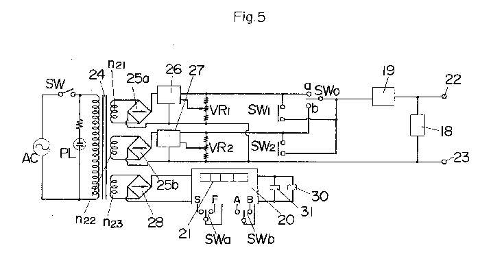
FIG. 4 is a perspective view of another embodiment of the invention;
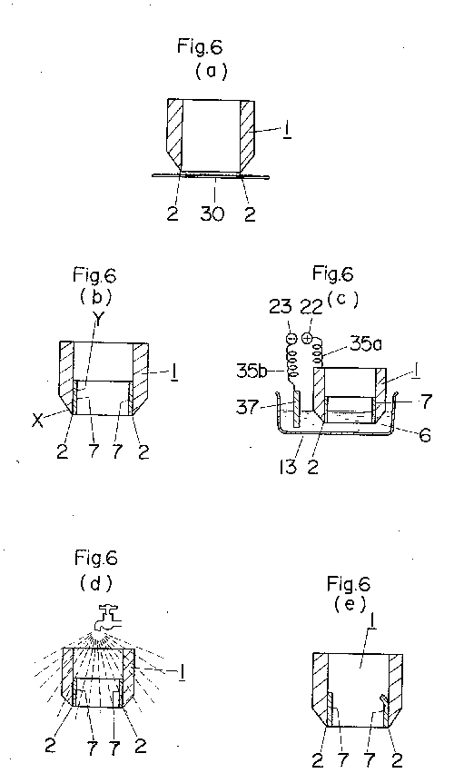
FIG. 5 is an electric circuit diagram of the apparatus shown in FIG. 4; and
FIGS. 6a through 6e illustrate a resharpening process at successive stages,
using the apparatus shown in FIG. 4.
DESCRIPTION OF THE PREFERRED EMBODIMENTS
FIG. 1 shows a cutting tool 1 of iron, which is to be resharpened according
to the present invention. The tool has a cutting edge of complex curve
formed by connecting numbers of concaves and convexes and is used for
punching out printed labels and the like. Therefore, manual or mechanical
resharpening of the edge 2 of the tool 1 takes much time and labor. FIG. 2
is a schematic sectional view of an apparatus according to an embodiment
of the invention. An electrolytic solution 6 consisting, e.g., of an
aqueous solution of 90% by volume of phosphoric acid and 1% by volume of
sulfuric acid is stored in an electropolishing tank 3. Support plates 5 of
insulating material for supporting cathode plates 4 extend over the tank
and between opposite sides of the latter. Two cathodes plates 4, made of
stainless steel, carbon, copper, lead or any other desired insoluble
metal, are suspended from the support plates 5, with their lower portions
immersed in the electrolytic solution 6, said cathode plates 4 being
connected to the cathode of a DC power source E of, e.g., 10 to 15 V.
Before resharpening, as shown in FIG. 3a, the cutting edge 2 of the tool 1
is blunt. Thus, a non-polished surface protecting film 7 is formed on the
non-polished side a at the back of the cutting edge 2 while leaving the
blunt area X exposed, as shown in FIG. 3a. Subsequently, the tool 1 is
supported by a support jig 8 at four places with bolts 9 so that the
cutting edge 2 is directed downward as shown in FIG. 3b. The legs 8a of
the support jig 8 are then placed on the support plates 5 disposed on
opposite sides of the electropolishing tank 3, with the cutting edge 2 of
the tool 1 immersed in the electrolytic solution 6.
Subsequently, the anode of the DC power source E is connected to the tool 1
and the cathode to the cathode plate 4, so that electric current flows
between the cutter 1, which is the anode, and the cathode plates 4.
Thus, the cutting tool 1 made of iron is subjected to electropolishing for
30 to 90 minutes, the solution temperature being 30.degree. C., the DC
power source voltage being 10 to 15 V, and the current density being 0.1
A/cm.sup.2. As a result, the surface unevenness, including nicks, of the
cutting edge 2 on the areas other than that covered with the protective
film 7 is removed, and a sharp edge 2 appears.
The protective film 7 is produced by mixing liquid vinyl acetate, varnish,
and a mixture of 40% by volume of phthalic acid and 60% by volume of
cellulose acetate, in equal amounts or 30% by volume each, adding 10% by
volume of toluene as a solvent to the resulting mixture to provide a mixed
synthetic liquid, applying the latter to the non-polished surface a of the
cutting edge 2 of the tool 1 prior to polishing or resharpening, and
allowing the same to stand at ordinary temperature for about 10 minutes
for natural drying. The film will not peel off the edge or droop, thus
ensuring attainment of a sharp polished edge. Upon completion of the
resharpening treatment, the film can be easily removed by hand without
using mechanical means or a solvent.
FIG. 4 shows another embodiment of an apparatus according to the invention,
and FIG. 5 shows electric circuitry incorporated in the apparatus shown in
FIG. 4. A box body 10 made of metal and top-opened, is sized to be
placeable on a desk and removably receives a tray made of synthetic resin
through the top opening. The box body 10 is provided with an operating
section 12 in the front. Support bars 15 of insulating material carry the
opposite ends of support rods 14 which suspend the cutting tool 1 to be
resharpened, said support bars being attached to and extending
longitudinally of the upper inner regions of opposite sides 11 of the box
body 10. The operating section 12 is installed between extensions 16 which
extend obliquely upward from the front ends of the sides 11, and houses
circuit components including a power transformer 16. Attached to the front
panel 17 of the operating section 12 are a voltmeter 18, an ammeter 19,
operating switches SWa and SWb, a time indicator 21 for a timer 20, an
anode terminal 22 and a cathode terminal 23. The power transformer 24
includes a secondary winding n21 for large current, a secondary winding
n22 for minute current, and a secondary winding n23 for feeding the timer
20, said secondary winding n21 for large current being adapted to provide
a secondary output of about 20 V, which is then rectified by a rectifying
bridge 25a to provide a DC output of about 10 to 15 V to a
constant-voltage circuit 26 whose setting is variable. On the other hand,
the secondary winding n22 for minute current produces a secondary output
of several volts, which is then rectified by a rectifying bridge 25b to
provide a DC output of several volts to a constant-voltage circuit 27
whose setting is variable. The timer 20 is an electronic timer composed of
LSI's and is adapted to operate by using as its power source a DC current
obtained by rectifying the secondary output from the secondary winding n23
by means of a rectifying bridge 28. The timer performs timing operation by
counting, as clock pulses, e.g., the commercial frequency of a commercial
power source AC. When an operating time is set by the time setting switch
SWa and the start-reset switch SWb is set to its start position A, the
timer will perform timing operation by turning on a time switch SW1 and
turning off a time switch SW2. Thus, when the time is up, it will turn off
the time switch SW1 and turn on the time switch SW2, such state being
maintained until the start-reset switch SWb is shifted to the reset
position B. The operating time and the amount of elapse of time are
digitally indicated by the time indicator 21, while in order to report the
expiration of the timing period, an indicator lamp 30 is lighted and a
warning buzzer 31 is sounded. The time switches SW1 and SW2 have one of
their respective ends connected to the anode terminal 22 through the
ammeter 19, the other end of said time switch SW1 being connected to the
plus output terminal of the constant-voltage circuit 26 and the other end
of said time switch SW2 being connected to the plus output terminal of the
constant-voltage circuit 27, so that the output of that constant-voltage
circuit which is now not connected to the anode terminal 22 will be
connected thereto when the time is up. The minus output terminals of the
constant-voltage circuits 26 and 27 are connected together and then to the
cathode terminal 23, while their plus output terminals are respectively
connected to the terminals a and b of a manual operating switch SWo, so
that such plus output terminal can be connected to the anode terminal 22
also by switching the manual operating switch SWo. The ammeter 18 is
connected between the terminals 22 and 23.
The way of using tool resharpening electropolishing apparatus will now be
described with reference to FIG. 6.
First, an electrolytic solution 6 in the form of an aqueous solution, e.g.,
of 90% by volume of phosphoric acid and 1% by volume of sulfuric acid is
stored in an electropolishing tank 13. Next, the cutting edge 2 of a tool
to be resharpened which is made of iron or alloys thereof (including
stainless steels), aluminum or alloys thereof, copper or alloys thereof,
nickel or alloys, thereof, or any other electropolishable metal is
polished with sandpaper 30 to smooth the edge 2, as shown in FIG. 6a. A
non-polished surface protecting film 7 is formed on the non-polished
surface Y at the back of the edge 2 while leaving the blunt region X of
the edge 2 exposed, as shown in FIG. 6b. The protective film 7 is made of
a mixed resin liquid prepared by mixing vinyl acetate, varnish, and a
mixture of 60% by volume of phthalic acid and 40% by volume of cellulose
acetate, in equal amounts or 30% by volume each, and adding 10% by volume
of toluene as a solvent to the resulting mixture, the latter being applied
to the back of the edge and allowed to stand for drying. Two parallel rods
14 support suspenders 34, by which the upper portion of the tool 1 is held
to hang therefrom. The support rods 14 are placed on support bars 15 to
extend between the latter. Thus, the tool 1 is suspended from the
suspenders 34 in the electropolishing tank 13, with the edge 2 of the tool
1 at the lower end thereof being immersed in the electrolytic solution 6.
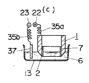
The tool 1 is gripped by a clip 36 which is connected to the anode
terminal 22 through a curled coil 35a, whereby the tool 1 is connected to
the anode terminal 22. A cathode plate 37 made of stainless steel, carbon,
copper, lead or any other insoluble metal and connected to the cathode
terminal 23 through a curled coil 35b is immersed in the electrolytic
solution 6 (FIG. 6c). Then, it must be decided whether the operation
should be performed manually or by using the timer 20. If it is desired to
perform the operation by using the timer 20, the operator sets the manual
operating switch SWo at the neutral and moves the time setting switch SWa
from its neutral position either to the slow position S or to the fast
position F to indicate an operating time in which the electropolishing is
to be completed (within 30 to 90 minutes), and then the operator moves
said switch back to its neutral position, whereby the operating time is
set and a zero time is indicated on the time indicator 21. The operator
then moves the reset-start switch SWb from its neutral position to the
start position A. Simultaneously with this operation, the timer 20 starts
operation, closing the time switch SW1 while leaving the now-opened timer
switch SW2 as it is. Therefore, the voltage from the constant-voltage
circuit 26 is applied between the anode terminal 22 and the cathode
terminal 23. This voltage can be set by a variable slide resistor VR1, and
the setting is such that the voltage is in the range of 10 to 15 V, at
which the proper current in the range of about 0.1 to 1 A/cm.sup.2 flows.
The voltage and current values are indicated by the voltmeter 18 and
ammeter 19, respectively. Thus, said current flows at ordinary temperature
(e.g., 30.degree. C.), so that the portion of the edge 2 not covered with
the protective film 7 dissolves out as metal ions to remove the surface
unevenness including nicks, thereby presenting a sharp edge 2. At the
expiration of the timing period, the timer 20 actuates the indicator lamp
30 and warning buzzer 31 to report the completion of resharpening.
Simultaneously with said expiration, the time switch SW1 is opened and the
time switch SW2 is closed. Therefore, the voltage to be applied between
the anode terminal 22 and the cathode terminal 23 is the output from the
constant-voltage circuit 27, the output current being tens of
milliamperes. This value is preset at the proper value by a variable slide
resistor VR2 in the constant-voltage circuit 27, and is effective to
maintain electropolishing at such a strength as to prevent the edge 2 of
the tool 1 from being attacked and deteriorated by the electrolytic
solution 6. When the reset-start switch SWb of the timer 20 is moved to
the reset position S upon completion of polishing, the time switches SW1
and SW2 are both opened and the timing period is reset. After resetting,
too, the time indicator 21, of course, renewedly indicates the present
time. The tool 1, which has thus undergone resharpening, is washed with
water, as shown in FIG. 6d, and the protective film 7 is then manually
removed to complete resharpening.
In addition, if the manual operating switch SWo is set to the terminal a, a
high voltage for electropolishing can be applied between the anode
terminal 22 and the cathode terminal 23, while if it is set to the
terminal b, a minute voltage for prevention of deterioration can be
applied between the anode terminal 22 and the cathode terminal 23. Shown
at SW is a power source switch and at PL is a power source lamp. In FIG.
4, the tool 1 has been shown as suspended by the support rods 14 bridging
the space between the support bars 15 on opposed inner lateral surfaces of
the body 10, but support plates 5 may be used, as in FIG. 2.
As has been described so far, according to the present invention, after a
protective film is formed on the non-polished surface of the edge of a
tool, the edge is immersed in an electrolytic solution and, with the tool
used as the anode, DC voltage is applied between it and the cathode
immersed in the electrolytic solution, for a predetermined time, so as to
resharpen the edge by dissolving the same. Thus, even recessed narrow
areas can be easily and positively polished and the rate of processing is
2-3 times as high as in the case of mechanical polishing devices, such as
files, and better finishes can be achieved. The protective film is formed
by mixing vinyl acetate, varnish, and a mixture of 60% by volume of
phthalic acid and 40% by volume of cellulose acetate, in equal amounts or
30% by volume each, to prepare a solution, applying said solution to the
tool and drying the same. Thus, the protective film, unlike paint or
adhesive agents, is free from drooping particularly at the cutting edge,
thus providing a sharp finish on the cutting edge. Further, upon
completion of resharpening, the film can be manually removed without need
to use mechanical means, so that the after-treatment step is shortened.
Further, since the electrolytic solution receptacle is removably received
in the box body, washing of the electrolytic solution receptacle can be
carried out separately from the box body, facilitating handling. Further,
the provision of support rods removably installed to bridge the space
between opposed lateral sides of the box body for suspending a tool to be
resharpened from the upper region of the electrolytic solution receptacle
makes it only necessary to suspend the tool in advance from the support
rods and place the latter in position when the tool is to be immersed in
the electrolytic solution. Further, when it is desired to withdraw the
tool, the support rods together with the tool may be removed from the box
body. Thus, tool mounting and demounting operation is easy. The provision
of the DC power source for passing DC current between the tool having its
edge immersed in the electrolytic solution and the cathode plate and of
the operating section integral with the box body saves need of wiring the
apparatus from a separate power source, makes the apparatus compact and
facilitates transport and installation of the apparatus.
Images
| United States Patent |
5,382,319
|
|
Tumminaro, Jr.
|
January 17, 1995
|
Solution and process for chemically resharpening smoothing tools,
forming tools and cutting tools
Abstract
This invention relates to a solution and process for chemically
resharpening smoothing, forming, and cutting tools such as files, jigsaw
blades, hacksaw blades, coping saw blades, bandsaw blades, and the like.
The solution contains preferred concentrations of phosphoric acid, anionic
and nonionic surfactants including ethyl alcohol and distilled water. The
tools are immersed in the solution for a period of 2 to 5 hours depending
upon the wear to the tools, after which the tools are removed, wiped, and
allowed to air dry to allow a rust resistant coating from the solution to
adhere to the tools.
| Inventors:
|
Tumminaro, Jr.; Anthony J. (P.O. Box 105, Gardena, ND 58739)
|
| Appl. No.:
|
133995 |
| Filed:
|
October 12, 1993 |
| Current U.S. Class: |
216/108; 252/79.2; 252/79.4 |
| Intern'l Class: |
C23F 001/00 |
| Field of Search: |
156/664,665,666
252/79.2,79.4
134/3,41
|
References Cited [Referenced By]
U.S. Patent Documents
| 4070193 |
Jan., 1978 |
Tucker |
156/666.
|
| 4668421 |
May., 1987 |
Dollman |
134/3.
|
| 4940493 |
Jul., 1990 |
Neidiffer et al. |
134/3.
|
| 5019288 |
May., 1991 |
Garcia |
252/79.
|
Primary Examiner: Dang; Thi
Attorney, Agent or Firm: Lingbeck; David A.
Claims
What is claimed is:
1. A process to chemically resharpen or sharpen forming, smoothing, and
cutting tools which comprises:
providing an aqueous solution of from about 1% to 20% by volume of anionic
and nonionic surfactant with ethyl alcohol, phosphoric acid of from about
5% to 92% by volume, and distilled water in a volume sufficient for the
balance of said solution;
completely immersing said tools in said solution;
subsequently removing said tools from said solution;
drying said tools; and
allowing a rust resistant coating of said solution to adhere to said tools.
2. A process to chemically resharpen or sharpen forming, smoothing, and
cutting tools as described in claim 1, wherein the step of providing said
solutions includes providing said solution with a temperature of greater
than 55 degrees Fahrenheit.
3. A process to chemically resharpen or sharpen forming, smoothing, and
cutting tools as described in claim 1, wherein the step of immersing said
tools in said solution includes allowing said tools to remain immersed in
said solution for a period of between 2 and 5 hours.
4. A process to chemically resharpen or sharpen forming, smoothing, and
cutting tools as described in claim 1, wherein the step of drying said
tools includes wiping said tools and air drying said tools for said rust
resistant coating to adhere to said tools.
Description
BACKGROUND OF THE INVENTION
This invention relates to a solution and process for chemically sharpening
smoothing tools, forming tools, and cutting tools, such as files and the
like, which are made of metal and can be used to smooth, form, or cut
wood, metal, plastic, laminate, and the like.
Conventionally, there are a wide variety of solutions and processes for
sharpening tools and blades. None of the prior art describes a solution
and process for chemically resharpening files and the like as described in
the present invention.
One known prior art is a BLADE SHARPENING SOLUTION AND PROCESS, U.S. Pat.
No. 3,492,178, comprising an etching solution of essentially ten percent
chromic acid, fifteen percent sulfuric acid, fifteen percent magnesium
hydroxide, fifteen percent aluminum hydroxide, three percent calcium
carbonate, two percent magnesium trisilicate, and thirty-four percent
distilled water into which stainless steel razor blades are immersed and
removed after a period of time and dried.
Another known prior art is a METHOD AND APPARATUS FOR RESHARPENING CUTTING
TOOLS BY ELECTROPOLISHING PROCESS, U.S. Pat. No. 4,406,759, which
comprises immersing the cutting tools in an electrolytic solution and DC
voltage is applied between the tool, which serves as an anode, and a
cathode plate immersed in the solution to thereby polish the edge of the
tools by dissolution.
Another known prior art is a METHOD AND BATH FOR ELECTROCHEMICALLY
RESHARPENING OF CUTTING TOOLS, U.S. Pat. No. 4,710,279, comprising an
aqueous solution of phosphoric acid and sulfuric acid to which is added
stabilizers of chromic acid, nickel carbonate and ferric oxide. An
electrical potential is applied to the cutting tool within the bath within
the range of one-half volt to six volts for a period of between one and
twenty minutes.
None of the prior art describe or even suggest the present invention of
resharpening forming and smoothing tools in addition to cutting tools
using a solution of chemicals not described or suggested by any of the
prior art. There is a definite need for a solution and process for
chemically resharpening forming, smoothing, and cutting tools and the
like.
SUMMARY OF THE INVENTION
The present invention relates to a solution and process for chemically
resharpening forming, smoothing, and cutting tools and the like. The
solution comprises preferably 18.75% phosphoric acid, 5% anionic and
nonionic surfactant containing ethyl alcohol, and 76.25% distilled water
thoroughly mixed therein, all of which is placed in a non-reactive tank
having side walls and a bottom wall. The tools to be resharpened can be
placed on a carriage having slots at the top to receive the tools and
having a bottom for the tools to rest upon. The carriage with the tools
thereon are lowered into the tank so that the tools are completely
immersed in the solution. The tools remain immersed in the tank for a
period of preferably 2 to 5 hours depending upon the degree of wear and
the types of teeth of the tools such as files and the like with the
average immersion time being 21/2 to 3 hours, after which the carriage is
removed from the solution and the excess solution is drained and the tools
dried to allow a rust resistant coating from the solution to adhere to the
tools which are preferably files but may also be router bits and other
miscellaneous tools.
It is an object of the present invention to provide a solution and process
for resharpening forming, smoothing, and cutting tools, in particular,
files, which saves the user of such tools money not having to always buy
new files as such whenever the old files become dull, the cost to
resharpen used files being in the range of 1/10 to 1/30 the cost of new
files.
Another object of the present invention is to provide a solution and
process for resharpening forming, smoothing, and cutting tools which is
safe for the user to use unlike the chemicals used in the prior art, which
are known to be harmful to the blood, bone marrow, and kidneys as such of
the user.
Also, another object of the present invention is to provide a solution and
process for resharpening forming, smoothing, and cutting tools, which is
environmentally safe to use.
Yet, another object of the present invention is to provide a solution and
process for resharpening forming, smoothing, and cutting tools, which is
simple to do and is relatively labor free.
Further objects and advantages of the present invention will become more
apparent as the description proceeds and when taken in conjunction with
the accompanying drawings wherein:
BRIEF DESCRIPTION OF THE DRAWINGS
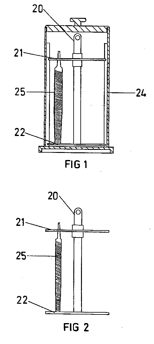
FIG. 1 is a sectional side elevation view of the non-reactive tank
preferably used in which the solution of chemicals or bath is placed and
showing a tool immersed therein.
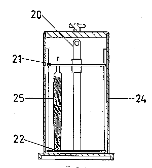
FIG. 2 is a side elevation view of the carriage means used, upon which the
files and tools can be placed for immersion in the tank containing the
solution.
FIG. 3 is a top plan view of the slotted plate mounted at the top of the
carriage, through which the files and tools can be inserted to rest upon
the carriage for immersion into the tank.
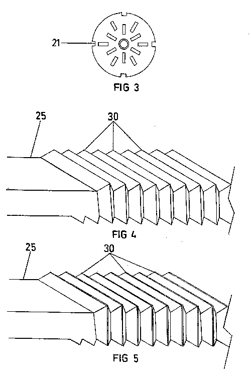
FIG. 4 is a breakaway side elevational view of the teeth of a file after
they have been resharpened by the bath of chemicals of this invention.
FIG. 5 is a breakaway side elevational view of the teeth of a file before
they have been resharpened by the bath of chemicals of this invention,
showing the dullness of the teeth.
DETAILED DESCRIPTION OF THE INVENTION
As demonstrated and illustrated in FIGS. 1 through 5 of the drawings, the
present invention relates to a solution and process of chemically
resharpening forming, smoothing, and cutting tools 25, in particular,
files as such. In a preferred embodiment, the solution should comprise
18.75% by volume of phosphoric acid; 5% by volume of anionic and nonionic
surfactant selected from the group consisting of (1) linear alkyl benzene
sulfonic acid, (2) sodium lauryl sulfate, (3) sodium dodecylbenzene
sulfonate, (4) ammonium lauryl sulfate, and (5)
alkylphenoxypolyoxyethylene; including ethyl alcohol; and 76.25% by volume
of distilled water, all thoroughly mixed together and placed in a
non-reactive tank 24 as is shown in FIG. 1, and the solution having a
temperature of at least 55 degrees Fahrenheit and having a volume great
enough so that the tools 25 are completely immersed therein.
As shown in FIGS. 2 and 3, the tools 25 can be placed on a carriage 20
having an upper slotted plate 21 fixedly attached thereto, through which
the tools 25 such as files can be inserted to rest upon a bottom plate 22
of the carriage 20. As shown in FIG. 1, the carriage 20 containing the
tools 25 are then placed in the tank 24 with the tools 25 being completely
immersed in the solution containing the chemicals for resharpening the
tools 25 which preferably should remain immersed in the solution for a
period of 2 to 5 hours, upon which the solution chemically resharpens the
tools 25 by evenly etching, carving, and cutting and sharpening the
cutting edges 30 of the tools 25 and after which the carriage 20 and the
tools 25 can be removed from the solution and tank 24, wiped and air
dried, and are ready for use with the once-dull teeth or cutting edges
resharpened as shown in FIGS. 4 and 5. The solution, in addition to
containing chemicals which resharpen tools 25 such as files and the like,
also comprises a rust resistant property which coats the tools 25 while
immersed in the solution. Once removed from the solution, the tools 25 are
wiped and allowed to air dry so that the rust resistant property coats and
adheres to the tools 25.
The strength of the solution and the number of times the solution can be
reused depends upon the concentration of the chemicals in the distilled
water. Heavier concentrations of phosphoric acid and the anionic and
nonionic surfactant including ethyl alcohol in the solution allows the
user to reuse the solution more times for resharpening tools 25. For
example, the solution can comprise 25% by volume of phosphoric acid, 8% by
volume of anionic and nonionic surfactant including ethyl alcohol, and 67%
by volume distilled water for reusing the solution more times to resharpen
the tools 25. Further, the solution can comprise 15% by volume of
phosphoric acid, 3.75% by volume of anionic and nonionic surfactant
including ethyl alcohol, and 81.25% by volume of distilled water for the
balance of the solution which is weaker and can only be reused fewer times
to resharpen the tools 25.
For effective resharpening of the tools 25 such as files the chemical
concentration of the solution can contain from 5% to 92% by volume
phosphoric acid, from 1% to 20% by volume anionic and nonionic surfactant
including ethyl alcohol, and the balance being distilled water.
As an alternate embodiment, the resharpening solution may comprise up to
95% by volume of hydrochloric acid with the balance being distilled water.
In such a solution, the tool or tools 25 should be left in the solution
for 2 to 15 minutes, after which the tool or tools 25 should be removed
and preferably placed in a solution comprising phosphoric acid to remove
any potential for surface oxidation of the tool or tools 25. The user
should use extreme caution when using hydrochloric acid in the
resharpening solution as it may cause serious injury to the user if the
user comes into direct contact with hydrochloric acid.
As another alternate embodiment, the resharpening solution may comprise up
to 95% by volume of chromic acid and sulfuric acid with the balance
comprising distilled water. As with the hydrochloric acid, chromic acid,
in particular is a harmful agent if the user comes into direct contact
with the chemical and extreme caution should be exhibited when handling
chromic acid.
Images
Method and bath for electro-chemically resharpening of cutting tools
| United States Patent |
4,710,279
|
|
Hozer
|
December 1, 1987
|
Abstract
A method and bath for electro-chemically resharpening of a metallic cutting
tool wherein the bath is composed of an aqueous solution of phosphoric
acid and sulphuric acid to which is added the stabilizers of chromic acid,
nickel carbonate and ferric oxide. An electrical potential is applied to
the cutting tool within the bath within the range of one-half volt to six
volts for a period of between one and twenty minutes depending upon the
type of part (size and construction) that is being resharpened. Preferred
temperature of usage for the bath will be approximately seventy-five
degrees Fahrenheit.
| Inventors:
|
Hozer; Norman R. (2085 Brookfield Dr., Thousand Oaks, CA 91362)
|
| Appl. No.:
|
020510 |
| Filed:
|
March 2, 1987 |
| Current U.S. Class: |
205/664; 205/680 |
| Intern'l Class: |
C25F 003/00 |
| Field of Search: |
204/129.55,129.9,129.95
|
References Cited [Referenced By]
U.S. Patent Documents
| 2868705 |
Jan., 1959 |
Baier |
204/129.
|
Primary Examiner: Tufariello; T. M.
Attorney, Agent or Firm: Munro; Jack C.
Claims
What is claimed is:
1. A bath for electro-chemically resharpening of metallic cutting tools
comprising:
an aqueous solution of phosphoric acid (approximately sixty-nine percent by
volume) and sulphuric acid (approximately twenty-five percent by volume)
to which is added stabilizers of chromic acid (approximately two grams per
liter), nickel carbonate (approximately five grams per liter) and ferric
oxide (approximately two-tenths gram per liter).
2. The method of electro-chemically resharpening of metallic cutting tools
comprising the steps of:
providing a bath consisting of an aqueous solution of phosphoric acid,
sulphuric acid, chromic acid, nickel carbonate and ferric oxide;
locating an electrode within the bath;
submersing into the bath the portion of a cutting tool that is to be
resharpened; and
applying an electrical potential between the electrode and the cutting tool
for a limited period of time.
3. The method as defined in claim 2 wherein:
the step of applying includes maintaining the electrical potential between
one-half volt to six volts.
4. The method as defined in claim 2 wherein:
the step of applying includes holding the period of time between one and
twenty minutes.
5. The method as defined in claim 2 wherein:
the bath is utilized at approximately seventy-five degrees Fahrenheit.
Description
BACKGROUND OF THE INVENTION
The field of this invention is related to electro-chemistry and
particularly to the electro-chemical milling of metallic parts.
The use of cutting tools, such as drills, routers, reamers and the like,
are in extensive widespread usage. A typical cutting tool is sharpest when
initially purchased. The shape of the cutting edge has been
pre-established at the factory and is honed to be as sharp as possible.
This cutting tool is then utilized at a finished stage of production. As
the tool dulls, the tool is then utilized at a final roughing out stage.
When the tool further dulls it is then moved to be utilized at an initial
roughing out stage which is frequently termed "hogging". When the tool
becomes unusable at this stage, the tool is either discarded or
resharpened.
Such tools are reasonably expensive. If a tool can be resharpened and
reused, generally that would be the most economical course of action.
Generally, this resharpening costs approximately one-half the initial cost
of the tool. This resharpening is accomplished manually utilizing a
grinding technique. There are machinists that specialize in resharpening
of tools.
The resharpened tool is normally used at the finishing stage. As the tool
dulls, it is then moved to the "hogging" out stage. Resharpening
significantly extends the life of the tool.
There are certain disadvantages to this manually resharpening of tools. The
first disadvantage is that it is a reasonably expensive operation. The
second disadvantage is that it is time consuming and normally requires
that the tool is shipped to an outside location from its point of usage
and is gone for a period of time during which it is resharpened. The third
disadvantage is that the resharpening technique is accomplised
frictionally. As a result, a significant amount of material is removed
from the tool. If the tool is cylindrical, the diameter of that tool is
significantly reduced, generally in the range of three to five percent.
Because of the amount of material that is being removed, the tool can only
be resharpened a few times before it becomes non-usable.
Previously, electro-chemical milling is well-known and comprises the
removal of material from the surface of a metal piece by the application
of an electrical potential in the presence of a conductive electrolyte.
This electrical chemical milling process is particularly well suited to
imparting a smooth finish to parts having surface irregularities. In the
past, electrical chemical milling has been utilized to deburr a manual or
mechanically sharpened edge, or in certain instances actually creating a
sharpened edge on a cutting tool. This process has found itself well
suited for resharpening of a file and in certain instances it has been
utilized to sharpen a cutting edge when utilized in conjunction with a
protective film applied to a portion of the tool that is being
resharpened. However, prior to the present invention it is believed that
it has not been known to utilize the electro-chemical process solely for
resharpening cutting edges.
SUMMARY OF THE INVENTION
The structure of the present invention has to do, in part, with the
arriving at a particular composition of electrolyte bath. It has been
found that, if an aqueous solution of phosphoric acid and sulphuric acid
be utilized, a desirable bath composition is obtained. In order to insure
stability of the bath between usages, it is necessary to apply stabilizers
in the form of chromic acid, nickel carbonate and ferric oxide. The bath
primarily is to be used at room temperature, but the bath can be increased
in temperature and therefore decreasing the time of usage that is required
to resharpen a cutting edge. An important consideration is to minimize the
electrical potential that is applied between the cutting tool and the
bath. If this electrical potential exceeds a certain level, the edge of
the cutting tool will assume a rounded configuration rather than a
sharpened configuration. Generally, a desirable level for the electrical
potential should be between one-half volt and six volts. The amount of
time that is required to effect the resharpening procedure is dependent
upon the type of material used and the physical size of the part that is
utilized as well as the number of parts that are located within the bath
at the same time. Generally, it is very rare that the sharpening time will
ever exceed twenty minutes.
The primary objective of the present invention is to utilize a method and
bath for electro-chemically resharpening of a metallic cutting tool
thereby eliminating the need for mechanical or manual resharpening.
Another objective of the present invention is to utilize an
electro-chemical resharpening method which resharpens tools near their
initial sharpened state thereby permitting the tools to again be utilized
at a finish stage of usage.
Another objective of the present invention is to utilize an
electro-chemically sharpening process wherein the amount of material
removed from the tool is significantly less than what is removed by
mechanical or manual resharpening thereby permitting the tool to be
resharpened a substantial number of times over that which was previously
possible by the mechanical and manual methods of resharpening.
Another objective of the present invention is to utilize an
electro-chemical resharpening process which permits cutting tools to be
resharpened in a short period of time and at a cost significantly less
than conventional mechanical or manual resharpening.
Another objective of the present invention is to provide a method of
resharpening of a cutting edge wherein complexity of the cutting edge is
immaterial so that a complex cutting edge can be sharpened as easily as a
simple form of cutting edge.
Another objective of the present invention is to accomplish resharpening of
tools by relatively unskilled labor.
BRIEF DESCRIPTION OF THE DRAWING
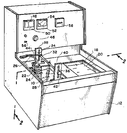
FIG. 1 is an isometric view of a form of apparatus within which is utilized
a bath of the present invention in order to achieve resharpening of
cutting tools; and
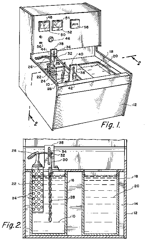
FIG. 2 is a cross-sectional view taken along line 2--2 of FIG. 1.
DETAILED DESCRIPTION OF THE SHOWN EMBODIMENT
Previously, when electro-chemical milling was applied to a sharpened
surface, such as a knife blade, it was known that the surfaces of the
sharpened edge eroded to some extent, but the erosion would tend to become
more concentrated at the point of the sharpened edge. As a result,
inherently with electro-chemical milling, a greater erosion occurred at
the point of the edge than at the side surfaces of the edge. Therefore,
electro-chemical milling would inherently produce a rounded edge as
opposed to a sharp edge.
Applicant discovered that with a certain composition of electrolyte bath,
and if the electric potential was used at low levels, that even erosion
would occur across the side surfaces of a cutting edge. No concentration
of the erosion would occur at any given point. The net effect is that with
a dull edge, which is where the sharpened edge has assumed a slightly
rounded configuration, the side surfaces of the edge will be eroded away
evenly substantially eliminating the rounded cutting edge and reproducing
the initially established sharp edge. The initial geometry of the side
surfaces of the cutting edges are maintained.
Maintaining of the initially established cutting edge within certain types
of tools is important in order to achieve maximum cutting efficiency
during usage. Frequently, during manual or mechanical resharpening, the
initially established geometry of the cutting edge is altered. Within the
present invention, the initially established geometry is maintained.
The using of electro-chemical milling in order to sharpen an edge has many
advantages. Some of these advantages have been previously discussed.
Another advantage has to do with when any edge is frictionally formed to
be sharpened there are apt to be metallurgical changes involved due to
heat and pressure causing loss of temper in some cases, brittleness and
chipping in others and/or burring. In stainless steel, these problems are
especially severe as stainless steel tends to drag to feather edges which
then must be removed without dulling the edge. This type of feathering
process involves a slow and expensive honing process to achieve the
desired sharp edge. Using of an electro-chemical sharpening process
eliminates all of these difficulties.
The electrolyte bath of the present invention can be utilized with a wide
range of alloys. If polarization occurs, which is common with carbides,
there is created a resistance on the surface of the edge which interferes
with the current path between the cathode and the tool. To overcome this,
it is necessary to remove the tool from the bath and rinse the tool in
water. The hydrogen in water depolarizes the tool. The tool is then
reinserted within the bath for completion of the electro-chemical milling
process.
When using a bath of the present invention in conjunction with stainless or
other types of carbon heat treated steel, it may be desirable to add
copper sulphate in the amount of approximately two grams per liter as an
added stabilizer. The use of the copper sulphate further stabilizes the
bath which seems to be necessary in conjunction with carbon heat treated
steels.
It will normally be desirable to replace consumed salts after a multitude
of usages of the bath of the present invention. The replacement of these
salts would be by adding of a small amount of conditioner which has been
specially formulated to replace these consumed salts.
The electrolyte bath 10 of the present invention is to be primarily
formulated of approximately sixty-nine percent phosphoric acid and
twenty-five percent sulphuric acid. One of the purposes for the sulphuric
acid is to achieve a polishing effect. Also, the sulphuric acid is to help
to smooth the sharpened surfaces. To this combination of phosphoric and
sulphuric acids there is to be added two grams per liter of chromic acid,
five grams per liter of nickel carbonate and two-tenths gram per liter of
ferric oxide. This bath is also to contain about six percent water. The
use of the sulphuric acid, the water and the stabilizing salts (chromic
acid, nickel carbonate and ferric oxide) enhances the phosphoric so that
the bath is able to accommodate a broader spectrum of different types of
alloys. It has been found that the bath 10 of the present invention is
able to handle exotic metals such as Inconel, Hastalloy, as well as other
types of exotic metals.
When a new tool is acquired, and is put to use, this tool has a sharp
fragile edge. After just a couple of passes with the tool the sharpness of
this edge will be slightly decreased to a working sharp edge. It has been
found that the resharpening procedure of the present invention in essence
resharpens tools to the level of this working edge.
It has been found that the time required to resharpen a cutting edge is no
more than five to ten minutes. However, in some instances, the time can be
increased to as high as twenty minutes. And still further, in certain
instances, there may be required an increased amount of time if the part
that is being sharpened is especially dull.
Using the bath of the present invention, the electro-chemical milling
process of this invention removes grind marks on the surfaces of the
cutting edge. This is desirable since these grinding marks will be
transformed onto the work piece. When dealing with high tolerances, it is
desirable to eliminate as much as possible these grinding marks. As a
result, on the workpiece there is achieved an improved micro finish.
If a tool that is slightly dull is resharpened with the bath 10 of the
present invention, the tool will be resharpened to achieve a super sharp
finishing tool. If the tool that is being resharpened has a higher degree
of dullness, it can be resharpened to a finishing tool. If the tool that
is being resharpened was rather abused and not usable, it can be
resharpened to at least a roughing stage tool.
Another objective of this invention is that tools can be resharpened
frequently without leaving the working environment. This means that the
tools are being used in a more highly sharpened state which improves the
quality of the workpieces.
Also, the bath 10 of the present invention can be utilized to slightly
reduce sizes of drills and reamers for special applications. In other
words, in certain instances it may be desirable to slightly reduce the
diameter of a drill or the reamer a few thousandths of an inch. The bath
10 of this invention can be utilized to achieve this end.
Referring particularly to the drawings there is shown a sheet material
housing 12 which is of a size to be located on a bench or other similar
type of supporting surface. This housing 12 includes an internal
compartment 14. Within the compartment 14 is located an open topped
container 16. The wall of the container 16 is electrically conductive. A
desirable material of construction for the container 16 would be copper.
Within the copper container 16 there is located a quantity of the
previously discussed electrolyte bath 10.
Located in juxtaposition to the container 16 is a second container 18.
Within the container 18 is located a rinsing bath 20 which will normally
comprise water. The material of construction for the container 18 would be
plastic or other similar type of material.
Immersed into the bath 10 is a metallic grid 22. This metallic grid 22 is
of an open box-like configuration with the electrolyte bath 10 being
constantly passing through the holes 24 of the grid 22. The grid 22 is in
contact with the copper wall of the container 16. In essence, the
container 16 as well as the grid 22 comprises a cathode. Electrical energy
is to be supplied through the conductor 26 to the grid 22.
The anode comprises the tool 28 which is to be sharpened. Only the cutting
edge of the tool 28 is to be submerged within the bath 10. The tool 28 is
attached by an electrically conducting wire 30 to a rod 32. The rod 32 is
mounted within slots 34 and 36 of the respective brackets 38 and 40. The
brackets 38 and 40 are fixedly mounted onto the housing 12. The rod 32 can
be adjusted within the confines of the slots 34 and 36 toward and away
from the surface of the bath 10. The tool 28 is mounted so that only the
desired sharpening edge of the tool 28 is submerged within the bath 10.
The rod 32 is then fixed in position with respect to the brackets 38 and
40 by means of tightening knobs 42.
Electrical energy is to be supplied to the rod 32 by means of conductor 44.
Conductors 44 and 26 connect to a source of electrical energy (not shown)
mounted within the housing 12. It is envisioned that this source will be
connected to a conventional one hundred ten volt source.
Mounted within the housing 12 is a potentiometer (not shown) which is
capable of being adjusted by turning of knob 46. The observing of the
amount of voltage is achieved by noting the position of needle 48 of
voltmeter 50 which is mounted on housing 12. Also, mounted on the housing
12 directly adjacent the meter 50 is a an ammeter 52. The reading of the
amperage is accomplished by knowing the position of needle 54. As by way
of example, for a reading of four volts observed by needle 48, a common
reading for needle 54 would be less than one ampere.
To apply electrical energy to the bath 10, it is only necessary to move
switch 56 from the "off" position to the "on" position. Also mounted on
the housing 12 is a counter 58. The counter 58 can be set to a
predetermined number of minutes which would be the estimated amount of
time that the tool 28 is to remain in the bath 10. At the end of that
period of time, an annunciator will be operated such as a bell to denote
to the user that it is time to remove the tool 28 from the bath 10 and to
stop the electro-chemical milling process.
Once the tool 28 has been completely removed from the bath 10 there is
normally not required any further steps prior to its usage.
* * * * *
Blade re-sharpener and method
| United States Patent |
6,488,834
|
|
Francis
|
December 3, 2002
|
Abstract
A razor blade sharpener utilising the principles of an electrochemical
cell. The blade (10) forms an anode (-) and a cathodic plate (16) is
provided in close proximity to the razor edge (12) to be sharpened. The
present invention electrochemically sharpens the edge (12) of the blade
tip (14) to provide a fresh, or "as new" razor blade.
The blade sharpener has additional uses for sharpening, for example,
kitchen knifes and surgical blades.
| Inventors:
|
Francis; Clive Alan (115 Langtons Meadow, Farnham Common, Bucks, GB)
|
| Appl. No.:
|
634361 |
| Filed:
|
August 9, 2000 |
Foreign Application Priority Data
| Current U.S. Class: |
205/652; 204/224M; 204/230.5; 204/271; 205/664; 205/674 |
| Intern'l Class: |
C25F 007/00; B23H 009/08 |
| Field of Search: |
205/664,652,674,224 M,230.5,271
|
References Cited [Referenced By]
U.S. Patent Documents
| 1721414 |
Jul., 1929 |
Robe |
205/664.
|
| 3438880 |
Apr., 1969 |
Martin |
205/664.
|
| 3696013 |
Oct., 1972 |
Tafapolsky |
205/654.
|
| 3762243 |
Oct., 1973 |
Borrkfield |
205/654.
|
| 4406759 |
Sep., 1983 |
Saitoh |
205/654.
|
| 4621669 |
Nov., 1986 |
Kiviman |
144/365.
|
| 4710279 |
Dec., 1987 |
Hozer |
205/654.
|
| Foreign Patent Documents |
| 779875 |
Mar., 1968 |
CA |
205/664.
|
| 860918 |
Apr., 1971 |
CA.
|
|
Primary Examiner: Valentine; Donald R.
Attorney, Agent or Firm: Salai, Esq.; Stephen B., Shaw, Esq.; Brian B.
Harter, Secrest & Emery LLP
Claims
What is claimed is:
1. A blade re-sharpener comprising:
a cathodic plate forming a cathode; and
means to hold a blade adjacente to the cathodic plate, to form an anode
such that a gap between the cathodic plate and the blade is very small
relative to the size of the blade.
2. A blade re-sharpener according to claim 1, wherein the blade comprises a
blade portion of a razor with substantially no dismantling of any handle,
packaging or casing thereof.
3. A blade re-sharpener according to claim 1, wherein the blade
re-sharpener comprises means for providing an electrolyte and a current
source connected, in use, to the cathodic plate and the blade, wherein, in
use, the electrolyte immerses both the cathodic plate and the edge of the
blade to be sharpened.
4. A blade re-sharpener according to claim 3, wherein the means for
providing an electrolyte comprises means for providing a sulphuric acid
solution.
5. A blade re-sharpener according to claim 3, wherein the means for
providing an electrolyte comprises means for providing a saturated
solution.
6. A blade re-sharpener according to claim 3, wherein the means for
providing an electrolyte comprises means for providing a blade sterilizing
solution.
7. A blade re-sharpener according to claim 6, wherein the means for
providing an electrolyte comprises means for providing sodium
hypochloride.
8. A blade re-sharpener according to claim 3, wherein the means for
providing an electrolyte comprises means for providing corrosion
inhibitors.
9. A blade re-sharpener according to claim 3, wherein the current source is
a solar cell, a DC power supply or a battery.
10. A blade re-sharpener according to claim 1, wherein the blade is one or
more razor blade of a disposable razor head, the anode being formed of the
one or more razor blade.
11. A blade re-sharpener according to claim 1 wherein the cathodic plate is
made of a conductive plastics material.
12. A blade re-sharpener according to claim 1, comprising a blade holding
portion for maintaining the gap, the blade holding portion having
insulating means provided thereon to prevent shorting of the
electrochemical cell across the gap.
13. A blade re-sharpener according to claim 1, wherein two cathodic plates
are provided, one for each side of the blade.
14. A blade re-sharpener according to claim 13, wherein a current source is
controlled to switch from one plate to the other plate.
15. A blade re-sharpener according to claim 1, comprising a current source
and a spring mounted probe, wherein, in use, the current source is
connected to the blade and the cathodic plate by means of the spring
mounted probe.
16. A blade re-sharpener according to claim 1, comprising a current source
and an electrically conductive wire, wherein the current source, in use,
is connected to the blade by means of the wire contacting a portion of the
front of the blade.
17. A blade re-sharpener according to claim 1 for a razor blade, comprising
a current source and an electrical connector, wherein, in use, the
connector forms a circuit between the current source and the blade, the
connector pushing the blade in a director away from a skin facing surface
of the blade.
18. A shaving box incorporating therein the blade re-sharpener of claim 1.
19. A combination of the shaving box according to claim 18 and a razor
having a handle and a blade attachable thereto, the box comprising a lid,
wherein the lid can be angled so as to angle the handle, when rested there
against, such as to position the blade of the razor against the blade
re-sharpener.
20. A blade re-sharpener for re-sharpening a razor blade of a disposable
razor blade head comprising:
a vessel for containing an electrolyte;
a cathode in the vessel;
a location for positioning the disposable razor blade head with its blade
adjacent the cathode such that the gap between the cathode and the blade
is very small relative to the size of the blades; and
at least one blade contact for contacting the blade of the disposable razor
blade head, the contact being connected or connectable to a source of
electrical current.
21. A blade re-sharpener for re-sharpening a blade that is mounted onto a
handle comprising:
a vessel for containing an electrolyte;
a cathodic plate in the vessel; and
a location for positioning the blade, with its handle, adjacent the
cathodic plate such that the gap between the cathodic plate and the blade
is very small relative to the size of the blade and
at least one blade contact for contacting the blade, the contact being
connected or connectable to a source of electrical current.
22. A method of re-sharpening a blade comprising providing a blade
re-sharpener having a cathodic plate, positioning a blade adjacent to
cathodic plate such that the gap between the cathodic plate and a blade is
very small relative to the size of the blade; providing an electrolyte for
the blade re-sharpener and connecting a power source across the cathodic
plate and the blade so that the cathodic plate acts as a cathode and the
blade acts as an anode.
23. A method of re-sharpening a blade according to claim 22 wherein the
electrolyte comprises sulphuric acid solution.
24. A method of re-sharpening a blade according to claim 22 wherein the
electrolyte comprises saturated saline solution.
25. A method of re-sharpening a blade according to claim 22 wherein the
electrolyte comprises a blade sterilizing solution.
26. A method of re-sharpening a blade according to claim 22 wherein the
electrolyte comprises sodium hypochloride.
27. A method of re-sharpening a blade according to claim 22 wherein the
electrolyte comprises corrosion inhibitors.
28. A method of re-sharpening a blade according to claim 22 comprising
providing two cathodic plates, one for each side of the blade and a
current source, and switching the current source from one plate to the
other during re-sharpening.
29. A method of re-sharpening a blade according to claim 22 in which the
blade is a razor blade of a disposable razor blade head.
30. A method of re-sharpening a blade according to claim 22 wherein the
blade is mounted onto a handle.
Description
TECHNICAL FIELD
The present invention relates to a blade re-sharpener. In particular, it
relates to a blade re-sharpener for producing a razor sharp, or "as new"
edge on a blade.
BACKGROUND ART
The primary reason for blades becoming blunt is that the extreme edge of
the blade bends over. With a cut-throat razor blade, such damage could be
corrected with the leather strip. New razor blade heads, however, have
their blades surrounded by plastic casings. Such correction of the edge
would therefore not be possible.
With continued use, the bent edge will actually break off resulting in a
permanently damaged blade. For shaving, such a blade edge is particularly
undesirable since shaving with such a blade inevitably results in facial
nicks and the like. Therefore it would be usual practice to dispose of
such a blade.
Typically, a modern razor blade head will last for a few shaves, and
perhaps up to one week of comfortable shaving. Thereafter, the blade,
although sharp enough to achieve shave, will not shave as efficiently or
as comfortably as when new.
Similar problems occur with other blades, such as those fitted to surgical
equipment, and kitchen knives. A means for restoring a clean, sharp edge,
which does not require aggressive sharpening with a grinder, for example,
would therefore be highly desirable.
DISCLOSURE OF INVENTION
An aim of the present invention is to provide a means for restoring a blade
to an "as new" condition thereby prolonging the life of a blade.
A device to achieve this would desirably function on disposable razor
blades, blade heads, kitchen knives, surgical blades and other such
blades.
The present invention provides a blade sharpener comprising at least part
of an electrochemical cell, wherein, in use, an anode thereof is formed by
a blade. The blade can be applied to the sharpener with preferably no, but
at least substantially no dismantling of the handle, packaging or casing
thereof.
Preferably the sharpener is a domestic blade re-sharpener, be they razor
blades or kitchen knives. However, the sharpener could be used in an
operating theatre for sharpening surgical blades.
Preferably, the blade sharpener comprises a cathodic plate, an electrolyte
and a current source connected, in use, to the cathodic plate and the
blade, wherein, in use, the electrolyte immerses both the cathodic plate
and the edge of the blade to be sharpened. This forms an electrochemical
cell. The process of electrolysis lifts the surface off the edge of the
blade to remove the bent over portion thereof, thus resulting in a
refreshed, or "as new" razor sharp edge.
Preferably, the current source is an external source of current, such as a
solar cell, battery or D.C power supply.
Preferably, the blade is a razor blade of a disposable razor head.
Preferably, the anode is formed of a plurality of blades, for example two
or three blades in a disposable razor blade head.
Preferably, the cathodic plate is stainless steel or a conductive plastic,
or nickel plated copper or solid nickel; little or no electrolytic action,
i.e. removal of material, will be experienced by the cathodic plate, and
therefore a variety of materials are appropriate. Indeed, the electric
circuitry may be formed entirely from conductive plastics, or may even
comprise printed circuits. The printed circuits may be conventionally acid
etched or may, for example, use conductive inks to make the circuit.
Preferably, the blade sharpener includes a blade holding portion which has
insulating means provided thereon to prevent shorting of the
electrochemical cell.
Preferably, the electrolyte is a weak solution of sulphuric acid, which
will also function as a descaler. Preferably, the electrolyte doubles as a
blade sterilizing solution and can have corrosion inhibitors provided
therein. The sterilizing substance could be sodium hypochloride. In fact,
most ionic solutions will work as the electrolyte equally as well as
sulphuric acid.
Two cathodic plates could be provided to sharpen a blade, such as a kitchen
knife on two sides thereof. Preferably, the current source would be
controlled to switch from one plate to the other plate to provide a
uniform sharpening of the blade edge.
Preferably, the gap between the cathodic plates and the blade edge is very
small.
In use the current source may be connected to the blade and plate, or
plates by means of a spring mounted probe. For a disposable razor blade
head, the probe may need to pass through vents provided in the back of the
disposable razor blade head.
The current source may be connected to the blade by means of a wire
contacting a portion of the front of the blade. For curved blades, the
cathodic plate(s) could be made to track/traverse the edge of the blade,
or this blade could be made to track/traverse the cathodic plate(s),
sharpening at the same time. This allows a disposable razor blade head
having a closed back to be sharpened using the present invention. Further,
since the connection forming the circuit between the current source and
the blade pushes in a direction away from the skin facing surface of the
blade, any indentation of the blade caused by the contact against the
blade will be in a direction which will not cause potentially hazardous
deformation of the blade, such deformations possibly causing skin nicks.
BRIEF DESCRIPTION OF DRAWINGS
Two specific embodiments of the present invention will now be described by
way of example with reference to the accompanying drawings, in which:
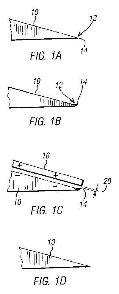
FIGS. 1A to D illustrate the process of sharpening achieved by the present
invention;
FIG. 2 shows, in perspective, a first embodiment of the present invention
for sharpening an open backed disposable razor blade head;
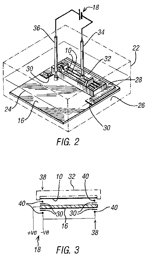
FIGS. 3 and 4 show an alternative universal embodiment for sharpening a
closed back razor blade head or other blade; and
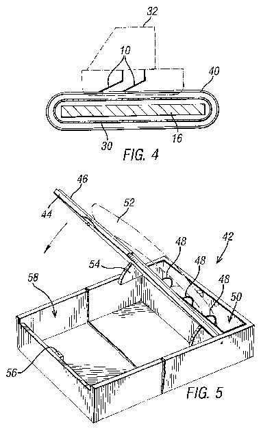
FIG. 5 shows a development of the present invention in which the embodiment
of FIGS. 3 and 4 has been incorporated into a shaving box.
MODES FOR CARRYING OUT THE INVENTION
Referring now to FIGS. 1A to D, the various stages in the life of a razor
blade 10 being processed by the present invention shall now be described.
FIG. 1A shows an "as new" blade edge 12, in section. The edge 12 has a
razor sharp tip 14 with no deformations thereon.
FIG. 1B shows the edge 12 of a razor blade 10 after use thereof. The tip 14
has been deformed by bending.
FIG. 1C shows a razor blade 10 and a cathodic plate 16 of the present
invention. The razor blade 10 forms an anode (-) and the cathodic plate 16
forms a cathode (+). The two items are immersed in an ionic conductor.
This ionic conductor, or electrolyte, may be a weak solution of sulphuric
acid, for example. These three components form an electrochemical cell,
which will perform electrolysis:
Fe (s).fwdarw.Fe.sup.2+ (aq)+2e.sup.- (aq)[steel blade reduction] Eq 1
2H.sup.+ (aq)+2e.sup.- (aq).fwdarw.H.sub.2 (g)[gas bubbles given off from
the plate]
This electrolysis reaction will result in a fresh edge 12 being formed for
the blade 10. This is done by means of electrolysis reduction of the anode
(-). Typically, a current source 18 to drive the electrochemical cell
could be a solar unit producing a current as low 180 mA and a voltage of
400 mV. This current, with a small gap 20 between the anode tip 14 and the
cathode (+), could effectively restore the edge of a used razor blade in
approximately half an hour.
By using a saturated saline solution for the ionic conductor, a more safe
cell is provided. Further, saline solutions are more readily available. A
saturated saline solution also makes the sharpening process work better
than the sulphuric acid solution as the saline solution works on chrome,
nickel and iron elements of the metal blade (as commonly found in modern
stainless or hardened steel blades), whereas the acidic electrolyte has
been found to work mainly on the iron (Fe) elements of the blade material.
Chrome and nickel metals are often added to, for example, razor blade
material in order to give, amongst other properties, corrosion protection.
Salt in solution is one of only a few substances that can corrode
nickel/chrome steels.
Combinations of two or more different electrolyte chemicals may also be
used to combine their effects.
FIG. 1D shows the razor after sharpening with the present invention. The
blade has effectively been restored to an "as new" condition.
Corrosion inhibitors could be provided in the electrolyte. Similarly,
sterilizing agents and descalers could be used.
Preferably, a blade 10 sharpened with the present invention should be of
high quality steel, which blades 10 are less susceptible to corrosion. For
example, stainless steel blades are ideal.
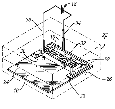
Referring now to FIG. 2, a first embodiment of the present invention will
be described. The present invention comprises a vessel 22 with an
electrolyte 24 (a solution of sulphuric acid) provided therein. On the
base 26 of the vessel 22 there is provided a cathodic plate 16. Mounted
onto the cathodic plate 16 there is a blade holder 28. The blade holder 28
is C-shaped and has provided under each arm thereof, extending slightly
inward from the arms, insulating strips 30.
The C-shape is sized to encapsulate three sides of a disposable razor blade
head 32, with the two insulating strips 30 providing seats for each end of
the disposable razor blade head 32. The thickness of the insulating strips
30 determines the size of the gap 20 between a razor blade 10 fitted in
the blade holder and the cathodic plate 16.
Instead of being C-shaped, the holder could be provided with a rectangular
cut-out or with retaining parts, or with any other means to retain the
razor blade head.
A lid of the vessel (not shown) can be closed onto the vessel 22. Two
contact probes 34, 36 extend down from the lid of the vessel 22. The first
probe 34, connected to a negative side of a current source 18, is
connected in circuit with the razor blade 10 through the back of the razor
blade head 32, and is biased against the blade 10 by a spring. The second
probe 36 is connected to the positive side of a current source 18 and is
connected in circuit to the cathodic plate 16.
Instead of providing two contact probes, any direct connection would
suffice.
When the cell is completed by immersion in the electrolyte 24, electrolysis
will occur. After a predetermined time within the cell, which time can be
determined empirically, the razor blade 10 will have been restored to an
"as new" condition as shown in FIG. 1D.
Referring now to FIGS. 3 and 4, a universal blade sharpener is provided.
This universal sharpener will function on disposable razor blades of the
type suitable for use with the first embodiment and also with disposable
razor blade heads which have sealed backs. Clearly the first probe 34 of
the first embodiment will not be able to connect in circuit through the
back of the razor blade head 32 if the back thereof is sealed.
This universal embodiment comprises a cathodic plate 16. Around two ends 38
of the cathodic plate 46 there are provided insulating layers 30 and wires
40 connected to the negative side of a current source 18. These wires 40
are spaced apart so as to contact only the end portions of the blade 10 to
be sharpened on the front thereof. Unfortunately, the blades 10 will not
be sharpened in the areas of contact with the wire. However, by means of
this "front application" design, many different blades, blade cartridges
and disposable razor blade head configurations can be sharpened. In
particular, it will sharpen both single, double and treble bladed systems,
irrespective of whether they have closed back casings.
This universal embodiment will also work with other blades, such as knives,
e.g. kitchen knives, by making the length and shape of the plate 16
correspond with the knife edge's length and shape. The shape and
configuration of the plate 16 may also be adapted to sharpen surgical
blades fitted to surgical instruments.
An advantage of providing the wire 40 on the outer face of the blades 10 is
that any damage caused to the blades by biasing the wires 40 against the
blade 10 will cause the blade 10 to deform away from the side of the
cutting edge which, in use, would be facing the skin of the user. This
provides a built-in safety feature for the device. In the first
embodiment, the blade contact is provided to the rear of the blade 10. If
the spring bias of the first probe 34 is too great, there is the risk of
deforming the blade 10 to an extent that it will potentially cause
undesired nicking of the user's face during shaving. Deformation caused by
biasing against the front of the blade 10 will not cause such problems.
In some instances, a spring may not be required to hold the blade head or
cartridge in contact with the wire 40; the weight of the handle of the
razor (or the like) may be sufficient. For an example of this, see FIG. 5
and the discussion thereof below.
In a preferred embodiment, the source of current 18 is a solar cell. This
typically will provide a DC current in the region of 180 mA and a voltage
of 140 mV. It has been found that this level of current and voltage is
sufficient to restore a blade 10 to an "as new" condition within about
half an hour. By changing the chemical strength of the electrolyte, the
current, the voltage or the gap 20 between the blade 10 and cathodic plate
16, different rates of electrolysis can be achieved and therefore the
blade 10 can be sharpened either quicker or slower.
The hydrogen gas generated as a by-product of the sharpening achieved by
the present invention is in very low volumes. Therefore, there is
little/no danger created by use of the present invention. Similarly, the
concentration of the electrolyte chemical, e.g. sulphuric acid, can be
very low, so that it also is not significantly dangerous.
Referring now to FIG. 5, there is shown a shaving box 42. The box 42
comprises a hingeable lid 44 into which may be mounted a solar cell 46.
The solar cell 46 is connected, by wires 48, to a blade sharpener, such as
that disclosed in FIG. 3 and 4. The blade sharpener is fitted to a base of
an end portion 50 of the box 42. The end portion 50 is fluid sealed so
that an electrolyte can be provided therein. A razor blade, mounted on a
handle 52, may be sharpened by placing the blade into the end portion 50,
together with electrolyte, so that the blade is appropriately orientated
relative to the blade sharpener. The lid can be angled so as best to
capture light and so as to angle the handle 52 and blade thereon against
the blade sharpener.
The lid 44 may be held in an open position by means of a ratchet mechanism
54 or by a prop (not shown). A latch 56 is provided to keep the lid shut
when not in use. A container portion 58 of the box is provided under the
lid 44. This container portion 58 may be sized to contain the handle 52
and razor blade, spare razor blades, shaving foam, and the like. The latch
56 keeps the container portion closed.
Although the shaving box disclosed herein has been described with reference
to FIG. 5, many features thereof are purely optional, although
advantageous. Modifications in detail thereof may, of course, be made
within the scope of the invention as defined in the claims.
In a fourth embodiment, not shown, two cathodic plates 16 could be used.
One plate 16 would be mounted on each side of the blade 10 for restoring
of both edge faces thereof. Clearly, this has desirable benefits for
sharpening, for example, kitchen knives. The current may be alternately
applied to each cathodic plate 16 in turn so as uniformly to sharpen the
blade 10.
Advantages of the present invention are that it not only restores a blunt
razor blade to an "as new" condition, but also the sharpening action is
non-aggressive. This prolongs the life of the blades by virtue that only
minimum amount of the steel of the blade is removed, whereas by aggressive
sharpening e.g. by grinding, or with a steel, the blade will quickly wear
down.
Further the action of the present invention generally will only remove the
high spots of the blade 10 which have been bent over by use. This is since
the gap is smaller at these points.
Further, there are no moving parts, or a need to move the blade by hand,
which undesirable features would potentially cause a risk to the user.
However the blade needs to be made from a material which is susceptible to
electrochemical reaction, i.e. electrolysis. Further, the first embodiment
is susceptible to problems if the rear side of the blade cannot be
contacted. However, the second embodiment provides a means for sharpening
these problematic blades.
It will be appreciated that the present invention could readily be adapted
for sharpening blades such as those found in surgical tools.
Preferably, the cathodic plate 16 is made from stainless steel or nichrome.
However, it is conceivable that conductive plastics could replace the
stainless steel or nichrome cathodic plate 16. This potentially could
reduce the cost of the materials required for making the present
invention. Further, the device would be lighter. An example of a suitable
conductive plastics material is PTS-Thermoflex-EC85/20*9900, provided by
PTS Plastic Technology Service Ltd of Flamstone Street, Bishopstone,
Salisbury SP5 4BZ, United Kingdom. This material is a thermoplastic
elastomer with a Shore A hardness of 80 and good electrical conductivity
due to 20% conductive carbon black.
The embodiments of the present invention disclosed herein are specifically
suitable for use in the home. The sharpener can non-intrusively sit on a
window shelf of a bathroom, for example, and could be used overnight for
sharpening a blade prior to use in the morning.
The present invention has been described herein purely by way of example.
Modifications in detail may be made within the scope of the invention as
defined in the claims.
